Building a basic PC with Intel's CA810E motherboard
Review date: 14 February 2000.Last modified 03-Dec-2011.
All-in-one motherboards have a bad reputation.
The idea is a good one, though. All IBM compatible computers use separate graphics, and probably also sound, hardware. Most of them have this hardware on sound and graphics cards, which attach to the motherboard - the central board that all of the other computer components connect to. Driver software for whatever Operating System (OS) the PC's running tells the OS how to talk to the graphics and sound card.
But the graphics and sound hardware doesn't have to be on separate cards. Graphics, sound, and maybe networking as well, can all be built into the motherboard. It still works much the same way - you still need the drivers for whatever kind of "cards" are built in - but you don't take up space, expansion slots and money with the extra paraphernalia required by the separate-card versions of the hardware.
All things being equal, the all-in-one approach leaves more room for specialised expansions, if the user wants them; if the user doesn't, the result is just a nice neat cheap computer which can be assembled from scratch in a startlingly short time. Sure, the built in graphics and sound aren't likely to win any awards, but as a plain basic computer it should be great.
Emphasis on the should.
Historically, all-in-one motherboards have been a big pain. The on-board hardware may be something outlandish which comes with poor drivers, or it may be close to but not quite the same as the stand-alone card version of the same thing. And if you want to upgrade, look out; all-in-one boards are famous for not letting you disable their built-in gear properly, and for not even having the expandability that comes with normal motherboards.
If you think a Compaq with "AGP graphics!" on the side of the box is definitely going to have an AGP slot, think again. That AGP graphics adapter is probably built into the motherboard, and there's no slot for a replacement.
Frankly, though, I think anyone who buys an all-in-one board with the intention of one day beefing up any of the things it has built in is missing the point. That's not what these boards are for. They're for saving money and making setup simpler, not for building red hot ninja computers.
Many people who find themselves unwillingly stuck with these machines have been tricked into it by some salesman who said an all-in-one machine was upgradable, without specifying exactly how. Sure, you can put in a bigger hard drive or plug in a new monitor or add a SCSI card or, probably, upgrade the CPU; there are all sorts of things you can add to an all-in-one. Just don't count on being able to improve the graphics and sound.
If you know what you're getting into, an all-in-one can be a great option. If an all-in-one board uses decent hardware and thus works properly out of the box, and you don't want to change the graphics adaptor or sound card or whatever else it has on board, it can end up being a rather good deal.
Intel's option
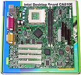
And here's a perfect example. Intel's CA810 series of motherboards all have graphics and sound built in. The graphics adaptor is a thoroughly capable 2D card, more than good enough for anything but 3D games on monitors as big as you like. For 3D its performance is not awful, but not exciting, either; it performs more or less like a good old Voodoo 2 card, except it can run in higher resolutions and numbers of colours. That's not a great idea, though; for decent frame rates, 800 by 600 in 16 bit colour is the go.
The built in sound hardware is the Sound Blaster 128 chipset, as seen on many cheap and cheerful sound cards. It's no good for fancy positional audio or studio MIDI work, but for this purpose it's perfect.
The current versions of the CA810 boards work with both Plastic Pin Grid Array (PPGA) and Flip-Chip Pin Grid Array (FC-PGA) processors (see my slotket review here to see what this is all about).
So you can plug any recent Celeron into them, and the new FC-PGA Pentium IIIs as well. Intel is going to migrate its entire P-III line to FC-PGA, so the CA810 line won't be starved for processors.
The original CA810 board only supported 66MHz Front Side Bus (FSB), so you could use it only with Celerons. The newer versions with a CA810A3 or CA810AL3 product code also support 100MHz FSB, so you can use 100MHz-based FC-PGA P-IIIs as well. These newer CA810s sell in Australia for $AU230.
The original CA810E supported 66MHz and 100MHz FSB, but the newer ones support 133MHz as well, making them compatible with the higher FSB "EB" Pentium IIIs, although none of these processors are yet available in the FC-PGA package. The only FC-PGA P-IIIs available as I write this are the 100MHz FSB 500E and 550E.
I checked out the top of the line CA810E, which comes not just with sound and video built in but also with the optional Intel 82559-based 10/100 megabit network adapter. This board sells for about $AU350.
With all of the built in gear, all you need to add to the motherboard is a processor and some RAM (standard low cost SDRAM modules). Plug in your drives and the case switch and light connectors, hook up the power, slap the case back on and you're in business. If you've never assembled your own computer before, this is about as simple as it can be.
The job of assembling a computer, though, can still be quite alarming to the newcomer. So here's the step by step guide.
Picking your parts
Step one is to pile up the other components. You've got the motherboard; what else do you need?
CPU
This is meant to be a basic computer, not a power user's machine, but the CA810E certainly gives you the option. It'll work with very fast P-IIIs, when they're available in the FC-PGA form factor. At present, though, they're not; the fastest CPU you can plug into the CA810E is a 550MHz P-III.
You're looking at about $AU650 for a P-III 550E, or about $AU500 for a 500E. That's a 30% price difference for 10% more CPU performance; remember, a 10% faster CPU doesn't give you a computer that's 10% faster overall.
The next step down for CA810 customers is a Celeron, which offers most of the performance for a lot less money. The 533MHz Celeron is not a lot slower than the 500MHz P-III for pretty much anything that anyone's going to do with an ordinary PC, but it'll only cost you $AU380 or so.
And if you're happy to buy a less zippy processor to be going on with, maybe because you're waiting for cheaper, faster FC-PGA P-IIIs to come out, then a 433MHz Celeron will set you back less than $AU200. It'll give you something like two-thirds of the P-III 550E's speed, for less than a third of its price.
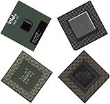
P-III on the left, Celeron on the right.
Intel had kindly provided me with a 500E along with the CA810E, but I had already found the P-III a high-speed home on an Abit BF6 (see my overclocking article here). The CA810 can't do any of the fancy tricks of the Taiwanese hot rod boards; Intel motherboards, oddly enough, absolutely will not run CPUs faster than their sticker speed. Funny, that. But I had a perfectly good 400MHz Celeron to hand, so onto the 810 parts pile it went.
A 400MHz Celeron is old enough, now, that you may have trouble finding one in the stores. If you can, expect to pay well under $AU200, and expect to be well pleased with the speed you get for your money. This CPU is more than adequate for games, business apps and image processing on any current OS you want to throw at it, including Windows 2000.
RAM
Because I was only using a Celeron, which runs from a 66MHz Front Side Bus, I only needed old-model PC66 SDRAM. You're not likely to be able to find RAM that slow in the shops at the moment, though; PC100 is the slowest on the shelves. RAM prices are set to fall pretty steeply in the near future as I write this; at present, though, a single 128Mb PC100 SDRAM module will set you back about $AU325.
(By the way, you can find a handy RAM price trend graph here.)
You can make do with 64Mb of RAM ($AU170 or so), but 128Mb is considerably nicer for Win95/98 and pretty much essential for Windows 2000.
And if you're planning to upgrade to a 133MHz FSB processor, or even if you aren't, PC133 memory costs only a little more than PC100.
Case
The biggest part of the PC is the box the other bits live in. But cases can be surprisingly inexpensive.
Because the CA810 boards use the microATX form factor, your case can be quite small. If you want to mount them in a big case you can do that too - the plethora of mounting points in all half-decent current cases mean you can fit pretty much any board into them - but for a basic computer, there's no point buying a huge tower case.
For this machine, I picked In Win's D500 desktop case. It's a microATX case with three 3.5 inch drive bays and a single 5.25 inch, and it costs only $AU110 including the little 145 watt Power Supply Unit (PSU) that's standard for microATX machines. 145W is well under spec for a high powered regular computer - 250W or 300W supplies are standard issue for serious machines, though many cases come with questionable 235W PSUs - but it's perfectly adequate for a basic machine like this.
Drives
I picked a yum cha Delta "44X" CD-ROM drive. Like all cheap CAV CD-ROM drives, its monster speed figure is quite optimistic - "44X" is almost 6.5 megabytes per second, and you're not likely to ever see it. But it only costs $AU85, slightly more than twice the price of the Panasonic 3.5 inch floppy drive I also added to the pile.
A Fujitsu "4.3Gb" hard drive for another $AU200 rounded out the package. I put the capacity figure in quote marks, because no hard drive actually has as much space as its specifications seem to imply. Hard disk manufacturers specify their drive capacities in millions and billions of bytes, not the numbers based on powers of two that they ought to use. A megabyte is 2^20 (1,048,576) bytes; a gigabyte is 2^30 (1,073,741,824) bytes. In real capacity, therefore, the Fujitsu clocks in at only 4Gb, and loses a few more per cent when you format it. Newcomers to do-it-yourself PC assembly often wonder where that extra drive capacity went; into the pockets of the marketing people, that's where!
Monitor choice
If you don't already have a monitor kicking around, the only choice for a true budget computer is a 15 inch screen. You can get perfectly good 15s for $AU300. If you're going to be using the computer a lot, a 17 inch monitor will let you use 1024 by 768 without squinting at fuzzy pixels, and only cost another $200 or so. 19 inch and larger monitors will, of course, work just fine with the CA810 - its built-in graphics adapter can output 1600 by 1200 2D video at a healthy 85Hz refresh rate, so for business applications and anything else that uses ordinary 2D video, the sky's the limit for monitor size.
For 3D, though, resolutions above 800 by 600 or, maybe, 1024 by 768 will be annoyingly slow on an 810 board, and considering the alarming prices of large monitors, you're not going to be buying one as part of a budget PC, anyway.
Other bits
You're also going to need a keyboard, mouse and set of speakers. Whether you get the el cheapo versions of all of these or go for a battleship IBM 'board, glowing Microsoft poseur-mouse and bassy three-box speaker system is up to you. Cheap and nasty versions of all of these components will often last for ages. You keep wishing they'd die, but they never do.
The 810 boards have USB and PS/2 ports, so you should get a PS/2 or USB mouse (PS/2, if you're using Linux, because Linux doesn't understand USB yet). Serial mouses on PCs have a nastily low sampling rate - the number of times per second the mouse position is updated. Likewise, you can use a PS/2 or USB keyboard. There's not much reason to bother with a USB one on a computer like this that's not going to be short of system resources.
If you go for the cheap options, then mouse, keyboard and speakers should cost you about $AU75 all together. Get the Rolls-Royce versions and you're talking $AU300 or more.
Building it
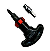
The tools of the trade. All you need to assemble a modern PC is a Phillips head screwdriver. This is my nice little Japanese made Vessel brand ratchet driver, but any old medium sized Phillips driver will do. The dingus above the driver is a 5mm socket, for tightening the hexagonal brass standoffs that the motherboard mounts onto, in most cases. The In Win D500 doesn't use these standoffs; it just has bumps in the base case metal that do the same job. If your case uses standoffs, and you don't have a 5mm nut driver, don't worry. Pliers do just as well - like everything else in a PC, you don't need to do them up too tight.
If you have big meaty fingers or just aren't too dextrous, you'll also need needle-nose pliers, tweezers with serrated jaws or hemostats (my favourite), if you need to adjust circuit board jumpers. You won't need to worry about this if you're building a basic computer, as everything can be left in its default state; there's only one jumper block on the CA810 boards, for BIOS configuration, and most users will only need to touch it if they set a BIOS password and then forget what it is.
The hemostat, commonly sold as a "scissor clamp" or incorrectly referred to as forceps, is the king of all jumper-yanking devices. If you use them, be careful, though; pliers and hemostats are eminently capable of crushing the fragile plastic jumper blocks.
Here we have the four kinds of threaded fastener you'll get in the bag of bits that comes with most cases. The one on the left is a fine-pitch screw used for mounting floppy and CD-ROM drives. These screws often have a combination head - a Phillips cross with half of the cross extended to fit an ordinary slotted screwdriver, like so:

Do not fall victim to the temptation to actually use a slotted driver on one of these screws. Flathead drivers are made by people in league with hardware manufacturers, who are delighted by their tendency to skate off the screw-head and gouge valuable computer equipment.
The other three screws all have the same coarser thread. Second from left is a coarse pitch short screw used for mounting hard drives (longer screws can thread in too far and damage the drive), followed by a hexagonal standoff that screws into the case and into which the motherboard mounting screws thread. The one on the right is the most common kind of screw; it's got a standard Phillips cross head. You use these screws for holding the case together, mounting expansion cards (which this basic PC doesn't need!), and mounting the motherboard itself.
Incidentally, if you're having trouble removing one of these last types, the hexagonal head shape outside the Phillips cross is a perfect match for a quarter inch nut driver. Quarter inch is the standard size for all hexagonal screwdriver bits, so any exchangeable bit screwdriver, including my nifty little ratchet driver and almost any cordless screwdriver you care to name, will fit. Cheaper versions of these screws have rounded shoulders on the hex head that stop you from getting a proper grip, but most of them work well.
You may also get one or more nylon things that look something like this. These are another kind of motherboard standoff, and should be used wherever a hole in the motherboard - maybe a roughly oval "double hole", maybe just a round hole bigger than the normal screw holes - coincides with a matching larger hole in the case.
Many cases have keyhole shaped cutouts that the nylon standoffs slide into, the idea being that you can leave them snapped into the holes in the motherboard and just slide it across a bit and lift it out. In the real world, the motherboard usually hits the case edge before the bases of the standoffs have moved far enough to disengage.
Nonetheless, nylon standoffs are good extra support for the corners of larger form factor motherboards, which usually have at least one corner flapping in the breeze far from a mounting screw. If you forget about this and, later on, push a connector on near that corner while the motherboard's mounted in the case, you can flex the board enough to break things.
Once you've got your tools and know what each screw type is for, it's time to open some boxes and prepare your motherboard.
RTFM!
The CA810 motherboards have most of their documentation on a CD-ROM, which is not too helpful if you don't have a working PC yet. But they, and every other motherboard out there, also come with basic paper docs that tell you what plugs in where.
Read The... Fine... Manual.
This tutorial tells you what to do and when, but in all likelihood the gear you choose to build your computer will not be the same as the gear I chose, and beginners may find themselves puzzled anyway. When something comes with instructions, read them. And take your time; if you're not sure about something, read the docs again, and have a think about it. It's not a race.
RAM and processor installation
It's easiest to install memory modules and the CPU when the motherboard's still out of the case. Both tasks are very easy with a Socket 370 board.
With the motherboard sitting on something with a bit of give - a newspaper on a table is fine - fold the memory module slot clips outward, line up a module so its edge connector matches the slot (there are cut-outs that make it only possible to install the module one way around), and press it firmly into place. The side clips will swing in and snap into place automatically. The CA810 boards have only two memory slots, but with 128Mb modules freely available this still lets you install plenty of RAM if you want to.
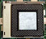
Installing the CPU is just as easy. Socket 370 boards use a "Zero Insertion Force" (ZIF) CPU socket. Swing up the lever beside the socket, and just drop the CPU into place. It only fits in one orientation. Swing the lever back down until it clips in place, and your CPU is mounted.
This Celeron had been in another machine, running faster than its stock speed, so I'd ditched the standard conductive pad that mounts on its heatsink and replaced it with thermal grease, as shown. For stock performance, the standard rubbery pads are fine.
Now, you clip on the processor cooler, the heatsink-and-fan arrangement that mounts on the top of the socket. This is easy to do, as long as you know that the CPU can stand a lot of pressure from its cooling hardware, so it's OK to apply a solid push to the clip to make it latch onto the catches on either side of the socket.
Here's the cooler in place; you can see one end of the clip at the right.
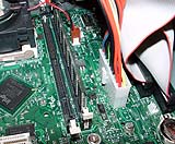
It's important to remember to plug in the processor fan cable to the connector provided, next to the RAM sockets. Otherwise your computer will work for a few minutes, then crash as the CPU overheats. No harm is likely to be done to anything but your sanity if you forget to plug the fan in.
Motherboard mounting
Now it's time to prepare the case and install the motherboard.
Like most desktop cases, the D500 is very easy to open. Just remove one screw from the middle at the back and the lid slides forward and hinges off.
If you'd rather it were a little harder to open, you can turn this gizmo at the back of the lid around. The loop will stick out through a slot in the case and you can snap a padlock through it.
It's easy to see what motherboard holes line up with what screw holes in a case, but there are often small chances to mess up.
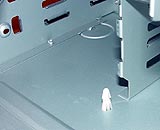
Like, for example, this one. This shows the one location in the D500, next to the drive bays, where you should install a nylon standoff if you're installing a CA810 board. There's another hole where a standoff can go, but it doesn't match a hole in the motherboard. So if you put a standoff there, you will have to employ pliers and profanity to remove it again.
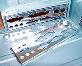
The back of ATX and microATX cases has a standard rectangular hole where you can install a plate with cutouts that match the connectors on your motherboard. Motherboards come with plates to match them, if they don't use the stock ATX connector layout. Here, I've removed the stock plate that came with the D500 and replaced it with the one that came with the CA810E. It's a simple snap-in replacement.
Because the D500 doesn't use the normal hexagonal brass standoffs, all you need to do is pop in the one nylon standoff, line up your motherboard, and screw it in place. Installing the brass standoffs in a less simple case is easy enough, too.
You may get, in the little bag of screws and stuff that comes with your case, a collection of fibre washers that fit onto the motherboard-mounting screws. You can use these washers if you like, or not; it makes little difference to the security of the motherboard, and none to the motherboard earthing. If you've got a tendency to overtighten screws, using the washers may help. Just mellowing out a bit will help more, though.
Drive mounting
Most cases have simple metal drive bays that you slide the drives into, then screw them in place through holes in the sides of the bays that line up with holes in the sides of the drives.
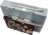
The D500, however, uses side rails that you screw onto the drives, which then clip neatly into the bays. This doesn't really take any less time than mounting drives the old-fashioned way, but it makes it easier to take them out again. The floppy drive is shown above...
And here are the CD-ROM and hard drive.
The floppy drive clips into this plastic cage that, itself, clips into the front of the D500. You don't need to remove the cage to install the floppy drive. If you want to install a second system fan, though, this is where you do it, in the box section at the bottom. A standard 80mm fan just clips into the box. I didn't see any need to do this for a low-spec machine like this; if you do, make sure the fan is aligned so that it sucks air into the computer, or it'll be fighting the exhaust fan in the power supply.
The hard and CD-ROM drives, installed in the bays to the right of the floppy/fan mounting cage. I installed the hard drive in the bottom bay to keep some air space between these two warm components. The perforated panel in the middle is the standard bay cover, which you have to pop out to install a 3.5 inch drive. There's no such cover for the single 5.25 inch bay.
Cables, cables, cables
You'll need to plug various things in now. The only really confusing part is getting the wide, flat "ribbon" cables for the drives around the right way. There's a red-striped wire on one edge of every ribbon cable; it denotes the side that should be connected to Pin 1 on each drive and motherboard socket.
This floppy drive, (mounted in a different case form the D500, so you can clearly see it) has the decency to clearly label the sides of the connector - the "2" and "34" printed beneath the projecting header at the left of the drive are the pin numbers nearest the printing. Pin 1 is at the top left, pin 2 at the bottom left. So you connect the pin-1, striped, side of the edge connector on the end of the floppy cable to the low-numbered side of the drive header. If you connect the floppy drive to the middle connector on the cable, it'll be identified as drive B instead of drive A (the twist in part of the cable between the connectors is what identifies the drives).
The drive with cables connected. The floppy drive is the only one that uses the smaller Berg power connectors from the power supply; all other drives use the chunkier Molex versions, as shown below. Both kinds of connector are keyed - you can only plug them in one way.
In case you're interested, the yellow wire is +12V, the red wire is +5V, and the black wires are both grounds.
These connectors are easy enough to attach, but sometimes stick fast in drive power sockets. The sockets are only held onto most drives by solder, so don't go nuts trying to wrench a seized power connector out. Prolonged fairly gentle wiggling should do the job.

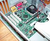
The CA810E has the standard three drive connectors - two 40 pin IDE connectors, one 36 pin floppy connector - in an unusual but handy staggered layout, with the floppy connector in the middle. The white connector to the left is the motherboard power socket, which the case power supply plugs into.
You only get one IDE ribbon cable with the CA810E, which is fine; two drives can be used from one IDE channel. Each end of the ribbon cable has a connector, and there's one more that's much closer to one end than it is to the other. The end with the two close-spaced connectors is for the drives; the other end is for the motherboard.
Motherboard ribbon cable connectors are always "keyed"; they have a small cut-out one one edge (the right edge in the image above) which mates with a protrusion on many, but not all, ribbon cable plugs. With keyed connectors, you can't go wrong unless someone's wired the cable backwards; you just plug the cable in the only way it'll go and you're done. With unkeyed connectors, you have to remember that when the key-slot is at the top, Pin 1 is to the left.
Some IDE connectors and cables are keyed in another way - Pin 20 is missing from the socket, and blocked in the plug. This makes it impossible to plug the connector in the wrong way around even if it doesn't have the slot-key protrusion, but cables with the blocked pin can't be plugged in at all if a socket doesn't have the corresponding missing pin.
When you've got two IDE devices on one cable, one has to be set to "Master" and one to "Slave". By default, hard drives come set to Master and CD-ROM drives come set to Slave, so nothing need be changed. The drive manuals show you what to do with the back-of-drive jumpers to change the mode.
It doesn't matter what order you plug the drives into the cable; the Master can be on the middle or the end connector.
Here's a hard drive using the middle connector.
If you want CD audio to be playable via the CD-ROM's normal analogue output - these days, this is pretty much only useful for playing audio CDs on your computer - you'll need to connect the CD-ROM sound output. The CD-ROM ought to come with a cable to do this, but they're close to free anyway. These cables are often not keyed at one or both ends - the sockets may be keyed, but the plugs aren't. But if you get them backwards, you just reverse the stereo channels and do no harm. The right signal wire is red, the left signal wire is white, the ground wires are black. Don't worry if your cable only has one ground wire.
Because of the CA810's onboard audio hardware, the other end of the CD audio cable goes to this motherboard connector. In most PCs, it goes to the sound card.
The ATX motherboard power connector can only plug in one way, and is all one piece. This may seem obvious, but it isn't; old AT-type motherboard power connectors came in two parts:
This is the way around you were supposed to connect them, with the black wires in the middle. Woe betide you if you got them backwards.
Fiddly little connectors
Ah, case connectors. These weeny little blighters attach to an equally fiddly header block on the motherboard, typically with cryptic labelling. If you refer to the manual you can figure it out; if you try to read the board you'll be flummoxed.
These little connectors are for all of the case lights and switches - the power and reset switches, the hard drive and power lights. There's also a speaker connector, which you need to hook up to most motherboards, but not the CA810 series...
...because they've got a speaker built in.
If you've got a dodgy case, the little connectors may be unlabelled. You can identify them by tracing them back to what they connect to on the front panel. Remember that the coloured, as opposed to white or black, wire is the positive one, meant to go to the first pin of that bit of the motherboard header. It doesn't matter if you get switch connectors backwards, as they'll still work, but the Light Emitting Diode (LED) lights only work if they're connected the right way around.
Finishing up
Because this computer needs no expansion cards, I screwed the included back panel slot covers in place over all four slots. This isn't just for neatness; case air flow works better if you block extra vents like this.
The finished, closed, box. Plug in keyboard, monitor and power and fire it up, and you should get a BIOS screen, which on recent Intel boards is a show-off piece:

...and you're ready to install your operating system!
Review CA810E kindly provided by Intel Australia.
