Building an LED caselight
Originally published 2001 in Atomic: Maximum Power Computing Last modified 03-Dec-2011.
OK, so you've got the stylin' case with the side window. And the multiple fans which may, at any moment, suck your video card out through one of the blowholes. And maybe even the water cooling rig, replete with expensive pearly silicone tubing.
As surely as a 1993 Honda Civic with implausible badges and "NOS" stickers must also have a coffee-can-sized exhaust tip, your computer must have a light inside it.
Want one that'll give you more than ten years of constant light and not take up much space?
Then you want LEDs, baby.
Ordinary 5mm high intensity Light Emitting Diodes top out at roughly penlight levels of brightness, per LED. But it's quite easy to make a very bright light by assembling an array of dozens of them. Alternatively, you can go for the new ultra-high-intensity "super-LEDs"; as I write this, the only ones available are Lumileds Luxeon Star lamps, which I talk about in more detail here. Electrically speaking, though, the Luxeon lamps work like regular LEDs; the numbers are just bigger. So you have to do much the same stuff to make a lamp out of any kind of LED, from a single 5mm LED to a giant array of Luxeon lamps.
LED primer
LEDs, of any size or shape, are quite easy things to work with once you know a few basic things about them, and about electricity.
LEDs are, basically, a bit like normal light bulbs. You pass electricity through them and they glow. If you pass too much electricity through them, they die. There are some important differences between LEDs and incandescent lamps, though.
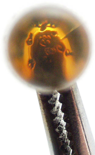
First, LEDs are diodes, so they have polarity; they only work one way. Ordinary LEDs (not Luxeons, or tiny surface mount LEDs) have a long leg and a short leg, as they come from the factory. The long leg of an LED is the positive one. If you connect the thing backwards, it won't do anything. It won't be hurt, either, though, unless you apply rather more reverse voltage than the LED normally runs from. Anyone who's assembled a computer and connected the case LED plugs backwards will know this already.
Second, LEDs need some resistance in series with them, either as part of the power source (if it's a small battery, for instance), or as a separate resistor. This is because LEDs have a death wish.
Incandescent lamp filaments have a positive temperature coefficient of resistance; when they get hotter, their resistance rises. They get very hot in normal use, and their resistance is much higher then than when they're turned off. Like, more than ten times as high.
LEDs aren't like that. They've got a negative temperature coefficient of resistance; the hotter they get, the lower their resistance becomes. And they warm up in normal operation - they're not magic 100% efficient electricity-to-light converters, but waste some power as heat, just like everything else.
If an LED is already passing enough current that a bit more power dissipation will kill it, and there's nothing - like a series resistor - to stop the heat-related resistance drop from allowing the LED to dissipate more power, you've got a situation called "thermal runaway", and your LED is not long for this world.

Overdrive an LED relatively gently and it'll briefly emit colours rather higher in the spectrum than the one it's meant to produce, and then die, with a very small sad sizzling noise. The thing you are left with after this may be referred to as a "friode".
If you overdrive an LED brutally, it'll still end up as a friode, but it will in the interim briefly function as an SED, or Smoke Emitting Diode.
Ex-SEDs are always open circuit - they don't pass any current - but more gently killed LEDs can end up short-circuited, which is worse. When a shorted LED is in a series string with other LEDs, they get to see all of the voltage that was meant to supply the whole string. This, of course, accelerates their own death.
Amps, volts and resistors
With reasonable heat-sinking, you can push more than 50 milliamps (mA, thousandths of an ampere) through modern high intensity 5mm LEDs, and a lot more through a Luxeon Star. Luxeon lamps, except for the bare-LED "emitter" version, all come attached to a small heat-sink circuit board. Ordinary LEDs are encapsulated in their epoxy lens, which is a good thermal insulator; their metal legs can conduct some heat away, but that's all they've got. Hence, less heat dissipation, even if you solder them to big fat conductive wires.
The rated safe-at-any-temperature current for 5mm LEDs is typically less than 30mA; 20mA is the usual current you'll see on the spec sheet.
That spec sheet will also tell you the nominal forward voltage for a given LED, which'll be around 2.0 volts for red and orange LEDs, around 2.2V for yellow and green ones, and substantially higher for the more expensive blue LEDs - they're generally rated at 3.0 to 3.6V.
White LEDs have similar ratings to blue ones, because they actually are blue ones - they have a phosphor layer over a blue LED die, which absorbs most of the blue and emits a range of other frequencies to give you a broad-spectrum white result.
You can wire identical LEDs in series or in parallel. If you're making a large LED array, you'll probably be doing both.
A parallel-wired array of LEDs - with each LED connected directly to the same power supply as if it were wired up by itself, and no electrons having to flow through one LED to get to the next - behaves, electrically, like one big unit with the same voltage drop as a single LED, but the current draw of all of the LEDs in the array put together. So, for instance, six 2V/20mA red LEDs wired in parallel will run from 2V, but will draw 120mA.
The brighter Luxeon Star LEDs have lower voltage requirements; leave a white Luxeon Star LED with just its standard heat sink, so it can get quite warm as the voltage rises, and you'll get 300mA current draw from little more than 3V - and the current can still rise another 50mA before you'll exceed the LED's specified limits.
Six of these LEDs in parallel will still run from 3V, but will draw 1.8 amps.
A series chain of LEDs behaves, electrically, like one unit with the same current draw as a single LED, but the voltage drop of all of the LEDs in the chain put together. So, for instance, six 2V red LEDs in a chain can be run from 12 volts. And six white 3V/300mA Luxeons in series will need an 18V supply, but still draw 300mA.
You can wire series LED arrays in parallel with each other, too. Take two chains, each containing six 2V 20mA LEDs, and connect them in parallel, and the resultant series-parallel array will run from 12V, and draw 40mA. Two of the abovementioned six-Luxeon chains put in parallel with each other will run from 18V and draw 600mA.
Because LEDs change resistance with temperature, though (see the "LED primer" box), you can't just connect a "12 volt" LED array to any old 12V power supply. Like, for instance, the 12 volt rail from your computer PSU.
Well, you can - if the LEDs really do start out drawing only 20mA, then they might well not get hot enough to kill themselves. But it's still not a great idea.
To take the edge off the thermal runaway problem, you use an in-line resistor, and a power supply with a higher voltage than the array wants. Resistors do not significantly change in value with the amount of current flowing through them. The resistor eats some of the volts, and damps the runaway by a varying amount, depending on its resistance value compared with the effective resistance of the LED array. In practice, you don't need a lot of in-line resistance.
The formula for figuring out what resistor value you need for a given LED, or LED array, is simple. It's basically just Ohm's Law.
Ohm's Law tells you exactly how any simple DC circuit like this will behave. It can be stated as V=IR - voltage (in volts) equals current (in amps) times resistance (in ohms).
Shuffled around to solve for R, this is R=V/I.
To find your series resistance value, you make V equal to the difference between the supply voltage, Vs, and the voltage you want across your LEDs, Vr. So here's that formula:
(Vs-Vr) / I = R
Let's say you've got a chain of three 2.2 volt LEDs (so Vr is 6.6) that you want to run at 25 milliamps (so I is 0.025, because there are a thousand milliamps in an amp) from a 12 volt supply (so Vs is 12). Now, the equation works out as
(12-6.6)/0.025=R
and R equals 216 ohms. 216 ohms isn't a standard resistor value, but 220 is; you can use resistors in series or parallel to exactly make up a non-standard value, but a 220 ohm resistor will work fine, here. The difference is small enough that it won't affect the numbers much.
The next thing you have to do is make sure your resistor can handle the job. Resistors come in many shapes and sizes, from tiny 1/8th watt and smaller ones to huge heatsinked multi-hundred-watt monsters. If you ask, say, a 1/4 watt resistor to dissipate one watt, you'd better have a pretty strong breeze blowing over it, or it'll burn up.
In this case, the resistor's dropping about 5.4 volts to give the LEDs the 6.6 volts they want, and it's passing about 25mA. Power (in watts) equals voltage (in volts) times current (in amps); 6.6V times 0.025A equals 0.165W. So a quarter-watt resistor would be fine in this application, but an eighth-watt would be overstressed.
Stuff you'll need
There are several things that you must have to make an LED caselight, and several other things that you don't have to have, but which help.
You'll need a soldering iron, for a start. Nothing fancy; a 20 or 25 watt sub-$AU20 cheapo-iron will do, as long as it's got a fine tip. Giant plumbing irons, soldering guns or metalworking irons that you heat up in a flame are not what you want.
If you don't have a soldering iron, all electronics stores sell cheap starter packs that give you a basic iron, a stand, a tip-cleaning sponge and some solder. Here in Australia, Jaycar's is catalogue number TS-1650, and costs $AU34.95. If you do have a soldering iron already, then you presumably also have these other accessories, unless you only use the iron for interrogation purposes.
You'll also need something vaguely resembling an ability to solder. If you've never soldered before, it's not hard to learn. There are lots of how-to-solder guides available online. Try here or here, for instance.
And you'll need a passing familiarity with elementary electronics concepts, like Ohm's Law. On-line guides like this one will tell you all you need to know.
Apart from the iron and accoutrements, the only tools you'll need are side cutters, for trimming component leads so they don't stick out on the other side of the circuit board like porcupine quills, and a wire stripper, if you don't think your teeth are up to it.
And you'll need some parts.

In this picture - LEDs, veroboard, a box, and a power connector cable.
First up, of course, are the LEDs. You'll need some.
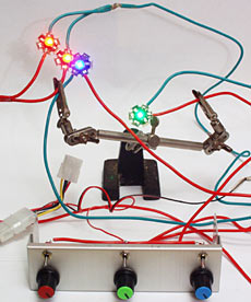
Your LEDs must be identical, if you want simplicity of design. You can have a light with multiple different flavours of LEDs if you like, and do all sorts of fancy switching tricks as well. But if you do, each flavour of LED should be on a separate circuit, in parallel with the others, with its own current limiting resistor.
I made an all-red-LEDs light, using Jaycar's ZD-1777 LEDs. They list for $AU1.45 each, for quantities of more than 25.
If you're building a red case light, you'll want more than 25 LEDs; the higher up the spectrum you go the more you'll pay per LED, but the fewer LEDs you'll need, thanks to the way the human eye perceives light.
Don't buy exactly as many LEDs as you think you'll need. Get a few spares. Especially if this is your first attempt at this sort of thing.
The box I used is Jaycar's HB-6005 clear project box, which costs only $AU2.95. Its frosted finish gives a nice diffuse light.
The cable-thing in the above picture is a PSU-to-three-pin adapter, which comes with various CPU coolers to allow people to run the CPU cooler fan in computers with no three pin headers on the motherboard. There are only two wires going to the fan connector, but they're all you need; they're +12V and ground. The third wire in a three-wire lead is the fan tachometer connection.
Hack apart one of these fan connectors and you get two wires terminated with neat-o pins that are about the right size for poking into a circuit board hole. And they're pre-wired to that pass-through four-pin connector, ready to connect to your computer PSU.
You can buy computer power connectors separately and wire 'em up yourself, of course. You could put a drive power receptacle on the side of your caselight's enclosure, or just hard-splice its supply wires into a PSU lead. But this is a straightforward solution, particularly when you consider that bare computer plugs and sockets can be a bit tricky to find.
You'll also need an appropriately rated resistor to suit whatever array you intend to make. Resistors are very cheap and available in a wide range of power ratings and values.
What do you attach all of the components to? Well, if you've got time on your hands, you can etch yourself a beautiful circuit board. If you're using Luxeon lamps, you'll probably have few enough components to deal with that you won't really need a board at all.
If you're using 5mm LEDs and you're not a raving perfectionist, though, you'll use...

..."veroboard". This is ordinary single-sided circuit board with a pre-applied multi-purpose copper pattern on it. It makes it quite easy to create simple circuits, like an LED array. It probably isn't made by Vero Electronics any more, but "veroboard" is a trade name that's stuck. It sounds better than "perforated stripboard prototyping medium".
If you want to make a really humungous LED array then you'll want a large-ish sheet of veroboard, like the big one in the above picture. The thing sitting on top of that, though, is Jaycar's HP-9556 "Ultra Mini" veroboard. This is actually two identical snap-apart boards, and it costs a big $AU3.80 for the pair.
If you're not confident about your resistor-picking and LED-soldering abilities, by the way, do a dry run with ordinary low intensity LEDs, which you can get for less than 15 Australian cents each if you buy a bulk pack of a hundred. These LEDs aren't bright enough to make it worth putting them in a box and trying to light anything up with them, but they work in basically the same way as their more expensive high intensity brethren, and veroboard's cheap enough that there's no need to even bother removing them when you've finished fooling around. Just get another board.

Also, get a multimeter. A $AU15 cheapie like the one in the above picture will be fine. Without one, you're left crossing your fingers and hoping that your LEDs are running at the current you think they are.
Now, the list of things you don't have to have, but which help.
A desoldering doodad of some sort. Unless you're naturally perfect, you will need to unsolder things now and then. It's much easier to do that, and to re-use the spot where the removed component was, if you've got something with which to remove the excess solder plugging the hole.
"Solder wick" is woven copper ribbon that sucks up molten solder. Spring-action solder suckers are also popular, and inexpensive.
While you're at it, get a second multimeter - or one fancy one with two sets of inputs. It's nice to have one meter in series with your LED array, telling you the current it's drawing, and another one across its inputs, telling you what voltage it's seeing. With two meters, you can watch what happens as the LEDs warm up, the current rises, and the voltage across the array falls. It's a blast. Seriously. Stop looking at me like that.
Got more spare money? Oh, good. Spend it on a variable-voltage power supply. For electronic-testing purposes, bench supplies with variable voltage and variable current are great; you can tell them not to supply more current than whatever you know is safe for the thing you're playing with. That's been experimentally proven to greatly reduce the number of friodes you'll produce.
Even a simpler supply with no current limiting is better than the fixed voltage from your PC. You can start it at a very low voltage and gently goose it up, watching the current draw on your series-connected multimeter, and stopping before anything can fry. Without such a setup, you can't easily test a half-built LED array.
For easier circuit board assembly, an adjustable vise like the Panavise Junior I used (Dick Smith Electronics have them for $AU30, catalogue number T4740) is also handy.
Laying it out
It's perfectly possible to just plunge into making an LED array - it's not like it's a time machine, or anything. The basic idea is pretty simple.
If I were you, though, I'd at least make sure I knew the rough board arrangement I was aiming for, and checked to make sure that every LED string started on a positive rail and ended on a negative one. Minor stuff like that.
If I wasn't writing an article about doing this, my layout sketch would have been a very back-of-a-beer-coaster sort of thing. But I am, so it isn't:

I decided on an array of 18 strings of two LEDs, which fit quite comfortably on this little board.
The red and black circles are where the power wires connect; note how the black one is on one of the little not-connected-to-anything two-hole islands, and is linked to the track I'm using as the positive rail by the array's current limiting resistor. It doesn't matter where the limiting resistor is in the circuit, as long as it's in series with the LED array.
With strings of only two red LEDs, I only needed a roughly four volt power supply for this array. So if I ran it from 12 volts, I'd need a current limiting resistor with a value of about 22 ohms. But it'd need to be able to handle the roughly 360mA I wanted to flow through the 18 20mA LED strings, and that meant it'd need around a three watt rating.
That's a rather chunky resistor, even if you can find an actual three-watter, and don't have to opt for a five watt wirewound. And I didn't want 2.88 watts of heat coming just from the resistor, plus the heat from the LEDs themselves, inside the sealed box.
So I rewired the power connector to connect to the five volt line from the PSU (the red wire) rather than the 12 volt (the yellow wire). Now the resistor only had to drop about one volt, instead of about eight. Sticking with the standard formula:
(5-4)/0.36=R
...gave a resistor value of about 2.8 ohms, and only 0.36W power dissipation, which is much more reasonable.
Putting it together
An LED array is a simple circuit. There may be a lot of components on the board, but you're just doing the same thing over and over.

Insert LED, make sure long leg is at the positive end, trim legs to length, solder.

I used a cut-clinch-and-burnish tool to cut the component legs off and smash them flat against the board, which effectively stops the LEDs falling off the board before you solder them. You can also, of course, solder and then trim, but that weakens the solder joint a bit.
[Note: About once every two years, someone reads this page and then e-mails me to ask where they can get their own cut-clinch-and-burnish tool. I've never actually seen one sold under that same name since I bought mine many years ago, but the model number on its sticker is "YYT-3", searching for which turns a few up. None at actual retailers, as I write this, but at least it's a lead.]

You don't need to be a soldering artiste to get it right, here. Make sure you don't bridge tracks that you don't mean to. Don't use a monster iron that'll lift the copper off the board. Take your time. Try not to breathe the lead vapour.
Don't worry about getting all of the LEDs lined up perfectly; you want a somewhat diffuse light anyway, and a frosted-plastic project box will hide any higgledy-piggledy component placement.
Note, by the way, the temporary contact wires tacked to the corners of the board in the above picture. They let me easily alligator-clip it to my bench supply to check it. They also let me test the completed array before I'd put its limiting resistor on.
Doing that showed me that, when it was cold, the array drew 234mA at 4.1 volts (2.05 volts across each of the LEDs in all of those 2-LED strings). Which was fine. When it warmed up, though, it drew almost 300mA at only 2.8 volts. There's that thermal runaway problem for you; if the array had still been provided with four volts, LEDs would be popping.
A bit of twiddling revealed that about 3.85V was a good input voltage to keep the LED strings at around 20mA each even when warm, which was where I wanted them to be. From a 5V supply, the resistor calculator formula worked out at 3.2 ohms with those numbers. 3.3 ohms is a standard resistor value and gave me a little extra safety room, so that's the resistor I used.

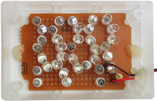
And here's the result.

The glamour-shot version.

And the back of the board. Note the clipped-off corners, to get the board to fit in the little project box.
Before you attach your power wires to the board, by the way, remember to thread them through a hole you've made in your project box. Poke the hole with your hot soldering iron if you're using an all-clear box; the clear plastic is likely to split if you try to drill it.
Plus, melting holes is fun.
A couple of dabs of hot-melt glue to hold the board down and provide strain relief for the cable, and it's time to screw on the lid.

Et voila.

The frosted lid works well as a diffuser.

The smoke test.
I wrapped the caselight in a blanket and left it running for a while; it peaked at 370mA. That's only 20.6mA per LED, about 450mW being dissipated by the resistor, and 1.85 watts total draw. Bewdy.
Oh, yeah. Does it work?

Yes. Yes it does. It's quite bright enough to make the case glow impressively in a normally-lit room.
It's easy to mount a little light like this with double-sided tape in various spots in the average case. It's certainly easier than mounting a neon tube.
At 20mA, the quoted life span for a common-or-garden high intensity LED is around 100,000 hours. That's over eleven years of continuous operation. If you only have your computer turned on for, say, eight hours a day, then you can triple that figure to get the light's service life.
At the end of their official life span, LEDs don't go ping and stop working, like an incandescent bulb. If you don't overdrive them, they just get dimmer and dimmer over a quite long period of time.
So I wouldn't be surprised if this thing were still be bright enough to use as a reading lamp after fifty years of continuous use.
The parts cost about $AU60. Less, actually, because the LEDs were on special. That's not bad life per dollar.
See also
How to build a Luxeon Star LED caselight!
URLs
Don Klipstein's site (lots of LED and other lighting info)
The Basic Soldering Guide Photo Gallery


![[SecureWebs]](images/sw.gif)